The buckling strength of a member depends on the buckling length. The buckling length depends on
- the system length
- the end conditions at the start and endpoint of the member. These end conditions can be supports
 or an adjacent structure
  .
.
The default assigned buckling lengths depend on how you’ve drawn the structure:
- If you draw a line of 5m and divide it in 5, each part will have a buckling length of 5m in both directions.

- If you draw 5 lines of 1m, each line will have a buckling length of 1m in both directions.

For some members the default assigned buckling length will be a safe assumption, for others not. Thus leaving the buckling lengths on their default value is not an option. The end-user must impose the correct buckling lengths. This can be done two ways:
- either impose them manually.
- either let Diamonds calculate them.
Both methods have their pro’s and con’s.
Workflows
This workflow should be relatively easy since it’s the method they teach you in school. It requires minimal knowlegde of the software, and if you know your buckling theory well, this method always results in a good approach.
- Determine the buckling lengths using tables, graphs, diagrams, … (like the one below).
These tables, graphs, diagrams offer a solution for simple support conditions. More complex support conditions like are usually not mentioned or require a lot of calculation work.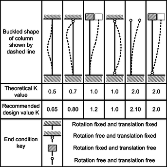
- Select the bar(s) for which you want to impose the buckling lengths.
- Click on
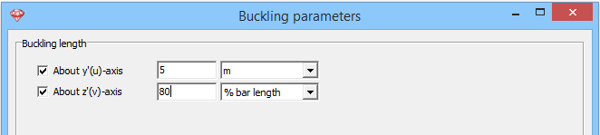
 and enter the desired buckling lengths in meter or a percentage for the bar length.
To let Diamonds calculate the buckling lengths:
- Define the groups for buckling.
- Click on
 to calculate the buckling lengths.
The dialog will show you 3 calculation methods in each buckling direction: displaceable, non-displaceable and semi-displaceable nodes. The choice of method depends on the material of the structure and the analysis method used.
For steel, see this article. For concrete and timber you could use semi-displaceable nodes. - Click on to see the calculated buckling length.
This method requires good knowledge of buckling length theory, the software and its limitations.
