A structure consists of supports and joints connecting the elements (= beam, column, plate, wall, …) in the structure.
- The way elements in the structure are connected with each other are called ‘joints’.
- The way elements in the structure are connected to the ground/ this planet are called ‘supports’.
Supports
Supports concern two aspects:
- The translational stiffness of a support: the resistance of the support against moving
- The rotational stiffness of a support: the resistance of the support against rotating.
Diamonds is 3D software, so a support has 6 degrees of freedom (DOF):
- Displacement in the direction of the global X-axis
- Displacement in the direction of the global Y-axis
- Displacement in the direction of the global Z-axis
- Rotation around the global X-axis
- Rotation around the global Y-axis
- Rotation around the global Z-axis
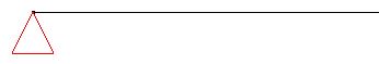
It’s possible to make an arbitrary combination in the limitations of the different DOF, but these 3 are used the most frequent:
| How it looks in real life | Mechanical representation | How it looks in Diamonds |
|---|---|---|
 |
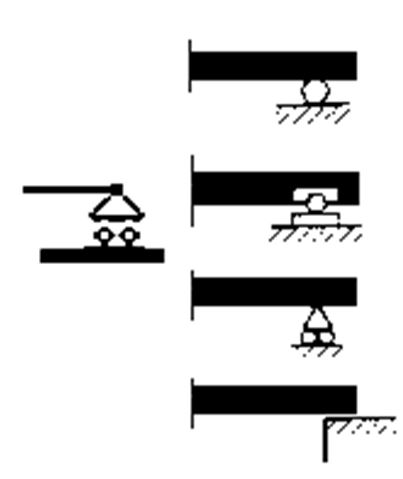 |
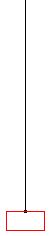
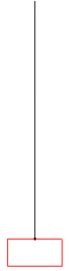
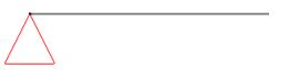
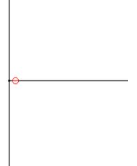
Roller support: displacement in the Y and Z-direction is fixed |
 |
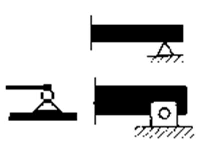 |
Pin support: Roller support: displacement in the X, Y and Z-direction is fixed |
 |
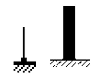 |
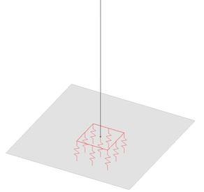
Fixed support: all displacements and rotations are fixed |
Joints
Joints (sometimes referred to as boundary conditions) are related to the level in which moments, normal and shear force can be transmitted between components itself.
Diamonds is 3D software, so a joint has the same 6 DOF as a support.
Although it’s possible to make an arbitrary combination in the limitations of the different DOF, an internal hinge (line) is used the most frequent. Here, the transmission of moment between the parts mutually is prevented.
| How it looks in real life | How it looks in Diamonds |
|---|---|
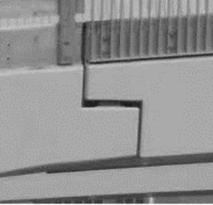
2 beam are connected with a tooth joint. This type of join is not capable of transferring moments. |
 A hinge was placed on one of the two beams. Not on both! A hinge was placed on one of the two beams. Not on both! |
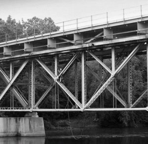
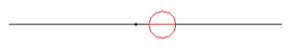
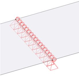
Truss bridge: no moment transfer in the nodes |
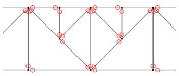
Hinges have been placed on the bar ends so no moment transfer can occur. If a node has N bars, there should be a hinge on N-1 bars. Not on N bars, because this results in a mechanism! |
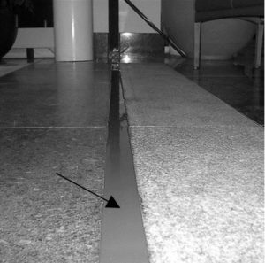
Thermal dilatation joint: in this type of joint the structure is cut into two parts allowing thermal dilatation. The connection between het two parts (often a rubber band) is not capable of transferring moments. |
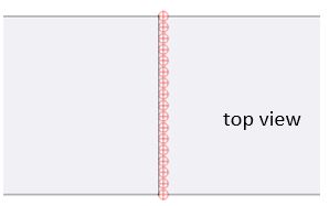
To simulate this in Diamonds, a hinge line was added to one side (it doesn’t matter left or right) of the slabs. Not on both sides because than it would be a mechanism! |
Boundary conditions between bars mutually can be defined using the button ![]() . Boundary conditions between a bar and a surface of between two or more surfaces can be defined using the button
. Boundary conditions between a bar and a surface of between two or more surfaces can be defined using the button ![]() . Default Diamonds assumes ALL components can transfer ALL type of forces. So if you want a fixed joint between two components, you don’t have to do anything specific, it’s default this way!
. Default Diamonds assumes ALL components can transfer ALL type of forces. So if you want a fixed joint between two components, you don’t have to do anything specific, it’s default this way!
Practical examples
| How it looks in real life | How it looks in Diamonds |
|---|---|
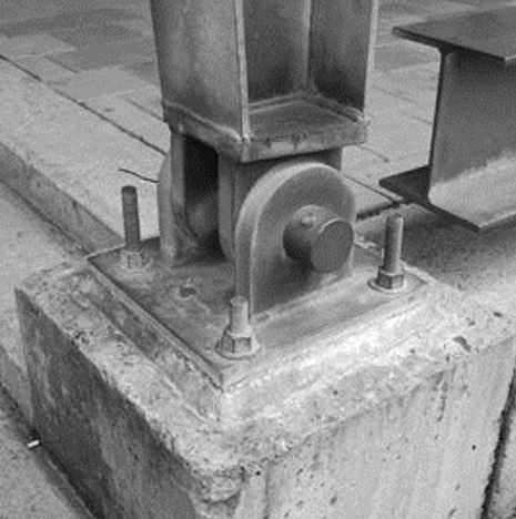
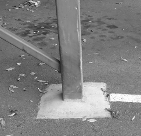
The column is connect to the foundation using reinforcement. The column and the foundation work as one unit. |
If the foundation isn’t modelled, itshould be replaced by a fixed support. |
If the foundation is modelled, supports should be added below it. This can be a spring constant or soil layers. The horizontal displacements in the global X and Z direction will be set fixed. |
|
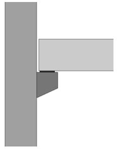
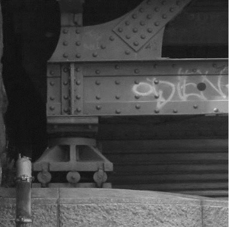
The beam rests on a corbel using a bearing pad. The bearing pad can’t transfer moments. |
If the column is NOT modelled, the beam should have a pinned support. |
If the column is modelled, the beam should have a hinge at his end. The corbel is not modelled in Diamonds. |
|
Two hollow core slabs rest on a beam (without a connection with reinforcement). The beam is supported by two columns. |
If the beam is NOT modelled, it can be represented by a pinned line support (if the bending stiffness of the beam is large in comparison to those of the plate). Between the hollow core slabs there should be one hinge line. |
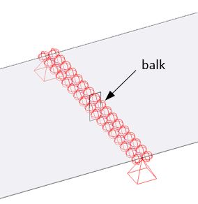
If the beam is modelled and the columns are NOT, then the columns should be replaced with a pinned support (eventual with a spring constant in the Y direction). Because now the beam is modelled between the hollow core slabs, two hinge lines are required. More information on the beam-plate interaction in this article. |
|
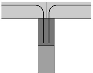
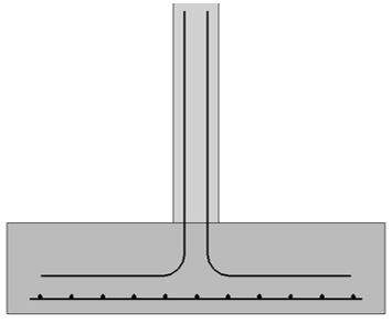
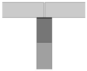
Two slabs are cast together with the beam below. The reinforcement (simply representation in the image) ensures the transfer of the internal forces between the beam and plates. This causes the cross section to act as a T -section. When loaded with bending, a compressive force will arise in the slab and a tensile force in the beam. The beam is supported by two columns. |
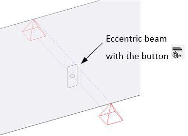
Because the slabs can work together with the beam as a T-section, the beam is modelled eccentric in Diamonds. More information on the beam-plate interaction in this article. |
